 English
 中文简体
中文简体What are the components of a cutter suction dredger?
Content
- 1 I. Dredging System: The Source of Power
- 2 II. Transport System: The Core of Fluid Transfer Transporting Crushed Material
- 3 III. Positioning and Lateral Movement System: Ensuring Precision During Operation
- 4 IV. Power and Control System: The Intelligent Brain
- 5 What is the working principle of a cutter suction dredger?
- 6 I. The Core Working Logic of a Cutter Suction Dredger
- 7 II. Key Steps Breakdown: The Journey from Seabed to Shore
- 8 III. Why are Cutter Suction Dredgers the Most Efficient?
- 9 Why is the cutter head called the "teeth" of a cutter suction dredger?
- 10 I. The "Terminator" of Hard Bottom Materials
- 11 II. Cutter Teeth Construction: Elite Armed to the Teeth
- 12 III. How Does the Cutter Determine Operating Efficiency?
- 13 IV. Intelligent Trend: Teeth with a "Brain"
- 14 What are the considerations regarding the material and design of the cutter head teeth?
- 15 I. The Soul of Materials: How to Find a Balance Between Hardness and Toughness?
- 16 II. Design Ingenuity: "Customized" Solutions for Different Formations
- 17 III. Ingenious Structure: A User-Friendly Replacement System
- 18 How does a cutter suction dredger maintain its position during construction?
- 19 1. Core Support Point: Steel Pile System
- 20 2. Powered Traction: Lateral Winch and Lateral Anchors
- 21 3. High-End Configuration: Steel Pile Trolley System
- 22 4. Auxiliary Methods: Three-Point Positioning and DGPS
In modern port construction, waterway dredging, and land reclamation projects, cutter suction dredgers, with their integrated dredging and transport capabilities, have become an indispensable national asset.
I. Dredging System: The Source of Power
The most prominent feature of a cutter suction dredger is its cutter head system at the front.
Cutter Head
Located at the end of the bridge at the front of the hull, it cuts underwater soil or rock through high-speed rotation. It is the key to determining the dredger's dredging capacity.
Cutter Drive Unit
Typically composed of a high-power hydraulic motor or electric motor, providing strong torque for cutting hard seabed materials.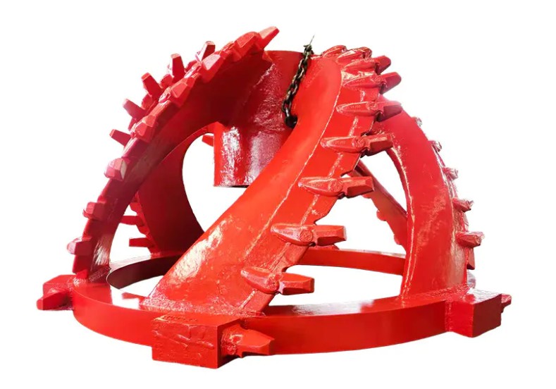
Ladder
This is a massive steel cantilever that supports the cutterhead, drive shaft, and underwater mud pump. Its raising and lowering controls the dredging depth.
II. Transport System: The Core of Fluid Transfer Transporting Crushed Material
Transporting crushed stone and mud from the seabed to the shore relies on the powerful mud discharge system of the cutter suction dredger.
Dredge Pump
This is the heart of the cutter suction dredger. It is typically divided into an underwater mud pump (to increase the suction concentration) and an in-hull mud pump (to provide delivery pressure).
Suction Pipe and Discharge Pipe
Mud enters the pump body through the suction pipe and is then transported long distances through the discharge pipeline connected to the stern.
Spherical Joints and Hose
In the above-water pipeline, these components ensure sufficient flexibility in wind and waves to prevent breakage.
III. Positioning and Lateral Movement System: Ensuring Precision During Operation
The cutter suction dredger does not move randomly during operation, but rather oscillates rhythmically like a compass.
Spud System
Two heavy-duty spuds are typically installed at the stern. The main spud serves as the rotation center, inserted into the mud, while the auxiliary spud is used for stepping movement.
Spud Carrier
High-end cutter suction dredgers are equipped with a hydraulic trolley, allowing the hull to move forward without lifting the spuds, significantly improving construction continuity.
Side Winches
These control the hull's left and right swing around the spuds via port and starboard tow cables, enabling fan-shaped excavation.
IV. Power and Control System: The Intelligent Brain
Diesel Engine / Generator Set
Provides energy for all mud pumps, hydraulic systems, and living quarters.
Integrated Monitoring System
Modern cutter suction dredgers are equipped with GPS positioning, production monitoring, and an automatic dredging system. Operators can precisely control the dredging trajectory and concentration via a touchscreen in the cab.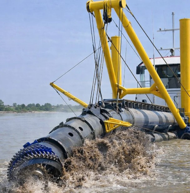
Understanding the components of a cutter suction dredger not only helps us comprehend the science of dredging engineering but also facilitates better equipment maintenance and performance optimization. From the robust cutter teeth to the sophisticated automated control system, every component is crucial to the project's progress and quality.
With continuous technological advancements, future cutter suction dredgers will evolve towards deeper dredging, longer discharge distances, and greater intelligence, continuing to shine in marine engineering.
What is the working principle of a cutter suction dredger?
I. The Core Working Logic of a Cutter Suction Dredger
The core working principle of a cutter suction dredger can be summarized as: "mechanical cutting, hydraulic lifting, and pipeline transportation."
In simple terms, it uses a rotating cutter head at the bow to break up the soil or rock on the seabed, mixing it with water to form a slurry. A high-powered mud pump then generates vacuum suction, drawing the slurry in and transporting it through a discharge pipeline to a designated shore or storage site.
II. Key Steps Breakdown: The Journey from Seabed to Shore
1. Rotary Cutting: Breaking Up the Bottom Material
At the start of operation, the bridge at the bow of the cutter suction dredger is lowered. The rotating cutter head at the end of the bridge rotates at high speed, driven by hydraulics or electricity. The carbide teeth on the cutter head, like giant teeth, cut and break up hard clay, gravel, and even hard rock.
2. Vacuum Suction: Slurry Formation
While the cutter head rotates, the suction port located behind it begins operation. Relying on the negative pressure generated by the mud pump (or underwater mud pump) inside the hull, the broken soil and surrounding seawater are rapidly mixed into a high-concentration slurry, which is then sucked into the slurry inlet pipeline.
3. Lateral Swinging: Fan-Shaped Excavation
The cutter suction dredger does not operate in a straight line. Instead, it uses a steel pile as the center, employing two lateral winches to pull steel cables, causing the hull to swing left and right in a fan-shaped motion. This "compass-like" operation ensures a flat and complete bottom surface.
4. Long-Distance Transport: Lifting Pressure
The sucked-in slurry is pressurized by a high-powered pump inside the hull. Utilizing the powerful discharge pressure, the slurry is transported over long distances through sealed discharge pipelines (including floating pipes, submersible pipes, and shore pipes), reaching distances of several kilometers, directly achieving "land reclamation."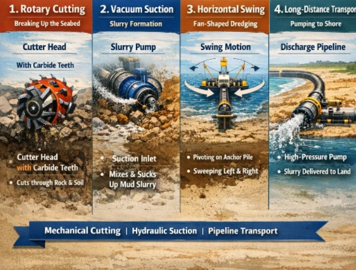
III. Why are Cutter Suction Dredgers the Most Efficient?
As the preferred vessel type for dredging projects, its advantages include:
- Continuous Operation: Unlike grab or trailing suction hopper dredgers, cutter suction dredgers eliminate the need for round-trip transportation; dredging and discharge occur simultaneously, resulting in extremely high efficiency.
- Wide Applicability: Whether dealing with loose sand or high-strength rock, a suitable cutter head can suffice.
- Environmentally Friendly and Precise: The controlled dredging trajectory minimizes disturbance to the surrounding waters and allows for precise depth control.
Understanding the working principle of cutter suction dredgers not only allows us to marvel at the beauty of modern industry but also highlights their crucial role in port expansion, waterway maintenance, and land reclamation. As a highly integrated and precise dredging device, it represents the pinnacle of contemporary marine engineering equipment.
Why is the cutter head called the "teeth" of a cutter suction dredger?
In large-scale dredging projects, cutter suction dredgers demonstrate astonishing construction efficiency. Structurally, the mud pump provides the "heartbeat" pressure that sustains the system's operation, while the cutter head, located at the very front of the working bridge, is the "tentacles" and "sharp blade" of the entire dredging system.
I. The "Terminator" of Hard Bottom Materials
The cutter suction dredger's ability to handle various geological conditions, from loose sand to hard rock, relies entirely on its sharp "teeth."
Mechanical Cutting Force: Driven by a high-powered motor or hydraulic system, the cutter head generates enormous torque. During rotation, the toothed seats and tips of the cutter head directly act on the bottom, fracturing dense soil layers, hard clay, and even granite.
Hard Rock Buster: Without the cutter head, ordinary suction dredgers cannot handle hard bottom materials. It is precisely these "teeth" that allow cutter suction dredgers to "break through mountains" in land reclamation projects, directly crushing underwater obstacles.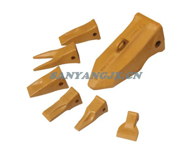
II. Cutter Teeth Construction: Elite Armed to the Teeth
Why are they called "teeth"? Not only because of their position at the front, but also because their construction is highly similar to that of teeth:
Extremely Robust Material: To withstand extremely high wear, cutter teeth are typically made of high-strength alloy steel, and sometimes even inlaid with hard alloys. This ensures that the "teeth" will not easily break or wear down when facing seabed rocks.
Replaceable Design: Just as a dentist can fill a tooth, the tips of the cutter teeth are replaceable consumables. For different geological formations (such as silt, dense sand, and weathered rock), engineers will replace the "teeth" with different shapes to achieve optimal dredging efficiency.
Multi-functional Shape: Chisel-shaped teeth are suitable for chiseling hard rock, while cutting edge teeth are suitable for cutting clay. This versatility ensures the flexibility of cutter suction dredgers in complex working conditions.
III. How Does the Cutter Determine Operating Efficiency?
Mud Concentration: The cutting effect of the cutter directly affects the mud concentration at the suction port. The more thorough the cutting, the higher the solids content of the mixed mud, and the stronger the conveying efficiency.
Precision trenching: Relying on the precise positioning and oscillation of the cutter head, the cutter suction dredger can surgically cut channel slopes that meet design requirements.
IV. Intelligent Trend: Teeth with a "Brain"
With technological advancements, the "teeth" of modern cutter suction dredgers are becoming increasingly intelligent.
Automatic Adjustment: Intelligent monitoring systems can adjust the cutter head speed in real time based on formation resistance, preventing damage from excessive load and significantly reducing energy consumption.
Wear Monitoring: Sensors monitor the wear of the tooth tips, issuing replacement reminders before the "teeth" fail, avoiding downtime risks.
What are the considerations regarding the material and design of the cutter head teeth?
I. The Soul of Materials: How to Find a Balance Between Hardness and Toughness?
The working environment of cutterhead teeth is extremely harsh, facing not only high-intensity impacts but also long-term frictional wear. Therefore, material selection is a core secret.
High-strength alloy steel: Most high-quality cutterhead teeth use special high-chromium-nickel alloy steel. This material undergoes a precise heat treatment process, achieving both high hardness to resist wear and high toughness to prevent brittle fracture upon impact with hard rock.
Hard alloy overlay: Under extremely high wear conditions, engineers will overlay hard alloy or inlay tungsten steel at the tooth tips. This "armed to the teeth" approach increases the wear life of the cutterhead teeth several times compared to ordinary castings.
Self-sharpening material design: Top-notch manufacturing processes allow the cutterhead teeth to maintain a relatively sharp shape during wear, a property known as "self-sharpening," which significantly reduces the energy consumption of cutter suction dredgers.
II. Design Ingenuity: "Customized" Solutions for Different Formations
Not all cutterhead teeth look the same. Depending on geological conditions, dredger component designers have developed various tooth shapes:
Chisel Teeth: Sharp, chisel-like in shape. Primarily used for excavating hard rock or weathered rock, breaking it apart through concentrated pressure at a single point.
Flare Teeth: Wide-edged, shovel-like. This design is best suited for excavating clay or loose sand layers, capable of cutting large areas of soil like butter, greatly increasing output.
Standard Teeth: Balancing cutting and impact capabilities, suitable for complex mixed geological formations.
III. Ingenious Structure: A User-Friendly Replacement System
Because cutter teeth are consumable parts, their structural design must consider construction efficiency.
Split Design: Modern cutter suction dredgers often employ a split structure of "tooth base + tooth tip." When the "teeth" wear down, workers can quickly replace the tooth tip using a special locking pin without cutting the entire cutter head, saving significant downtime for dredging projects.
Hydrodynamic Design: The design of the cutter teeth also considers the fluidity of the slurry. A scientifically designed shape reduces rotational resistance, making it easier for the slurry to enter the suction pipe, thereby increasing the suction concentration of the slurry pump.
How does a cutter suction dredger maintain its position during construction?
1. Core Support Point: Steel Pile System
This is the primary positioning method for cutter suction dredgers. Two massive steel piles, vertically penetrating the hull, are typically installed at the stern.
Main Pile: During construction, the main pile is lowered vertically and deeply inserted into the seabed mud. Like the "needle" of a compass, it firmly anchors the hull to the water surface, serving as the rotational center for the entire vessel's lateral dredging movement.
Auxiliary Piles: Primarily used for "stepping" pile replacement. When a fan-shaped area is excavated and further progress is needed, the auxiliary pile is lowered to a fixed position, while the main pile is raised and moved forward. The two piles work alternately, allowing the dredger to move forward precisely, like "walking with crutches."
2. Powered Traction: Lateral Winch and Lateral Anchors
Two lateral anchors are deployed diagonally forward from both sides of the dredger.
By maneuvering the lateral winches on the dredger and releasing the steel cables on both sides, the dredger sways in a fan-shaped pattern, pulling the bow left and right around the main pile.
This "one pile, two anchors" layout forms an extremely stable triangular support system, ensuring that the dredger does not violently sway due to reaction forces when cutting hard rock.
3. High-End Configuration: Steel Pile Trolley System
Large or advanced cutter suction dredgers (such as the "Tianjing") are also equipped with steel pile trolleys.
Principle: The main pile is not directly fixed to the hull, but rather mounted on a hydraulically movable trolley.
Function: With the main pile inserted into the soil and stationary, the hydraulic cylinders can propel the entire hull forward (typically by 3–9 meters). This means the vessel can continuously excavate without frequent pile replacements, greatly improving positioning stability and construction efficiency.
4. Auxiliary Methods: Three-Point Positioning and DGPS
Three-Point Positioning: Under certain specific conditions, in addition to steel piles, stern or side anchors are used to form a multi-point combined positioning system to cope with strong currents or extreme waves.
Spatial Positioning: Modern cutter suction dredgers are equipped with DGPS (Differential Global Positioning System) and various sensors to monitor the precise position of the hull relative to the designed channel in real time, with errors typically controlled to the centimeter level.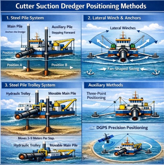
The secret to the cutter suction dredger's stability lies in "using the pile as the axis and the anchor as the force." The steel piles provide solid vertical support, while the horizontal anchor provides precise horizontal control. The combination of the two makes this cutter suction dredger as stable as Mount Tai in the surging waves.
Copyright 2025 Taizhou Sanyang Heavy Machinery Co., Ltd. All Rights Reserved Non-Standard Heavy Machinery Products Manufacturers

Back To Top